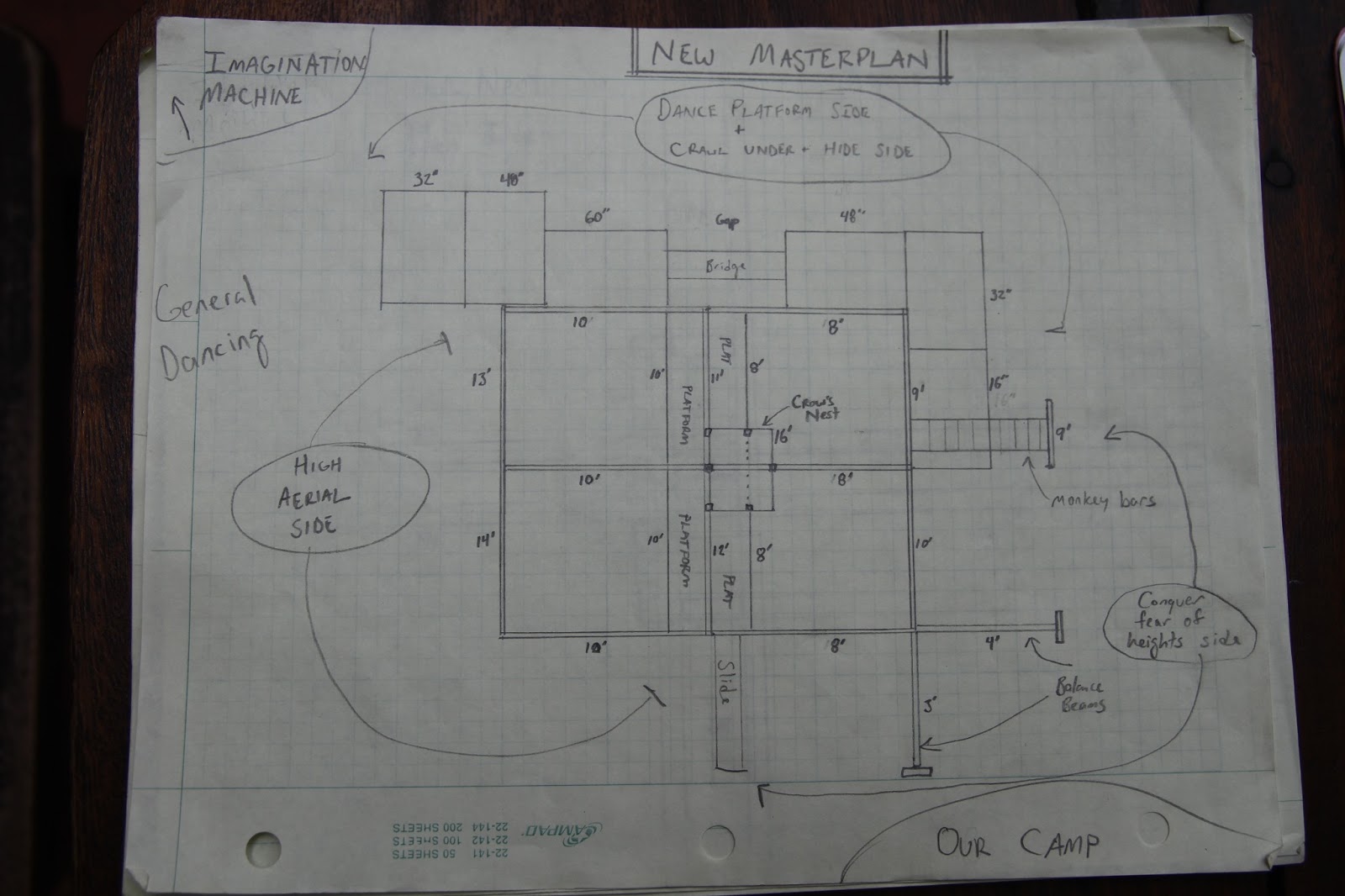
Ok, this is my newest, cleaner version of the masterplan with more platforms, other elements and the wider context with the Imagination Machine and our camp depicted. If this were placed just where we were placed last year at Apo, the big tree would be in the upper right, the main road where it says "NEW MASTERPLAN", the imagination Machine would be where it was, and our camp similar as well.... all along the bottom side of this drawing.
The Crows Nest: I think we should try to do this. I think it would be awesome for a bunch of reasons, and not that much more work. It can be tied in pretty easily to the existing base structure without too much fancy bracing. It can be accessed from the 10' high platform just left of center, and extend up to 16'. That way it is the tallest part of the structure, you can pass beneath it on the 8' platform, and it seems very tall when you look over the right side of it, 16 feet down to the ground. With a railing on three sides (top, right and bottom here) it is safe enough. It would also be a great thing to attach aesthetic things like flags, draping down to the sides, and lighting.

This shows an approximation of what the middle of the structure would look like with extra timbers coming up to support a crow's nest platform. The details of how we tie in everything can be figured out more precisely though... especially how to tie in railings. You get the idea though.

Sorry I can't rotate this. Probably could with more time, but getting ready to fly out in the morning.
This is the more detailed drawing of the "AB" arch.
Things to note: each arch is a pre-fab piece that is screwed and glued for stability.
There are two ERRORS on this drawing.
1) The slots for the AE beam and the BF beam should be designed for 2"x8" pieces, not 2x6.
2) The long allthread and bolt depicted in the middle of the right side should not connect all the way through the "C" post. It needs to only connect the bottom of the 45deg brace to the "B" post. The B and C posts are bolted together, as accurately depicted above and below.
So, this is the shortest arch. Each arch has a taller one paired with it. The CD arch pairs with this one. Each short arch of the pair includes top beams that extend laterally beyond itself so it can attach to it's taller neighbor. That is depicted here with the dashed-line "C" post shown.

Everyone still with me? And again, this is just what I"m designing over here in Asia. Let me know what you think.

This one was previously published, but just wanted a slightly better picture, and with the little text box indicating that the measurements all over the page are the height of whatever element, whether a post, a cross beam, whatever. The dashed lines in the middle indicate a set of platforms at 8ft, and a set at 10ft off the ground. This is also to use as a reference for the other drawings (like the "AB" arch).
Hopefully this all gives everybody a pretty detailed working idea of what I would like to see us pull off. It's a lot of sawing, screwing, and bolting, but not super crazy. Things to be done next:
0) Critique, tweak, give your building, engineering, construction, expert, and hunchy opinions!
1) Estimate how much 2'x6' we need for all of the 6 arches (it's all 2x6 as designed.) And what sizes.
I haven't done detailed drawings of each arch, but each can be extrapolated from the one that I did detail (the shortest one). Each one simply gets one foot progressively taller.
2) Estimate how much 2'x8' we need for all 8 of the super simple attaching crossbeams. They can all be identical.
3) Estimate the screws and bolts needed for this (Horsey... you probably have the best idea).
4) Start either ordering shit, or buying stuff to prototype an arch. I'm a bit worried about weight. These are designed to transport whole, and they get big! We need to be able to move each one with 4 guys max.
No comments:
Post a Comment